What is FORM-FLEX® coupling?
Features of FORM-FLEX® couplings
Feature 1. No lubrication required
- FORM-FLEX® couplings have no sliding, friction, or rolling parts, so no lubrication is required.
Therefore, in addition to being noise and wear-free and with low energy losses, they are also clean and oil-free.
Feature 2. Fit and forget
- When properly installed and if the initial conditions remain unchanged, it will have a long life. Required maintenance consists of a visual inspection of the flexible element and confirmation of the tightening condition of bolts and nuts when not in operation.
Feature 3. Light weight and high torque
- FORM-FLEX® couplings offer a wide range of options depending on the operating conditions.
Further weight reduction can be achieved by changing the main body material to aluminum alloy and the spacer to one made of composite (CFRP).
Feature 4. Large misalignment tolerance
- Wide misalignment tolerance allows for flexible adaptation to a variety of systems.
A special design also allows for even larger misalignment tolerance. The allowable range of misalignment varies depending on the coupling model, so choose according to your usage conditions.
Feature 5. Lower thrust load and bending moment
- The main aim of FORM-FLEX couplings is to absorb shaft misalignment while transmitting torque.
Absorbing misalignment puts a load on the shaft as a reaction force. The reaction force varies depending on the operating conditions, but it is kept quite low compared to that of other couplings.
Feature 6. Backlash-free, high torsional rigidity
- For machines such as machine tools with NC devices, indexing devices, and printing machines requiring accurate shaft rotation and phase control, FORM-FLEX couplings are the best fit because of their backlash-free structure and high torsional rigidity.
Feature 7. Excellent environmental resistance
- Since no lubrication is required, operation in high temperature atmospheres is possible even with standard materials.
Furthermore, the use of special materials and coatings allows operation in even harsher environments. Contact us regarding usage conditions such as corrosive environments.
Feature 8. Strong structure, low load stress
- The load stress of FORM-FLEX® couplings is kept at extremely low levels, except in special cases. Therefore, if it is selected correctly and within the allowable misalignment range, they will have a long life.
Feature 9. Easy to mount and dismount
- They have a small number of parts and are small and compact, allowing for quick and reliable mounting and dismounting.
They also allow for quick reassembly.
The spacer allows the coupling to be easily mounted and dismounted without moving heavy equipment. This is very useful for replacing seals and bearings in pumps, etc.
Feature 10. Fail-safe mechanism
- Even if the element is damaged due to overload or sudden accident, the fail-safe mechanism that transmits rotation through the washer will function and take care of it. However, since operation using the fail-safe mechanism is an emergency measure, restore the normal structure as soon as possible.
Structure of FORM-FLEX® coupling
Simple structure ensures long life
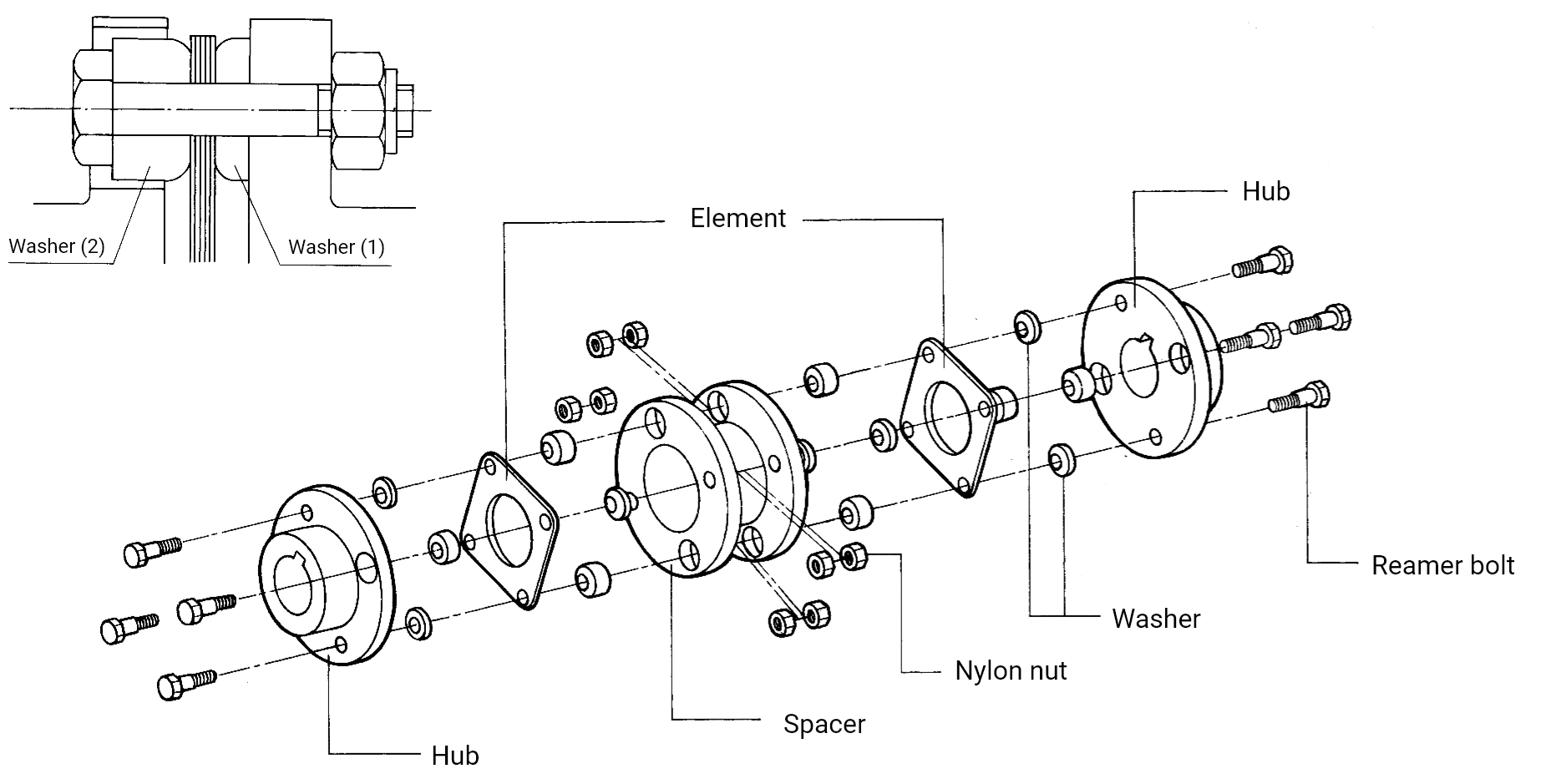
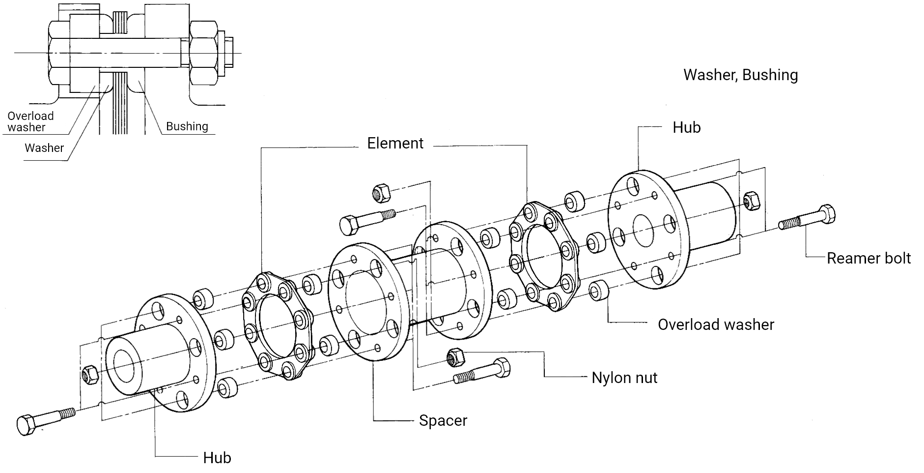
The double flexing coupling, which is a typical structure of FORM-FLEX couplings, consists of three principal components: a hub, a spacer, and a flexible element. This extremely simple construction ensures the high torque and long service life of FORM-FLEX® couplings.
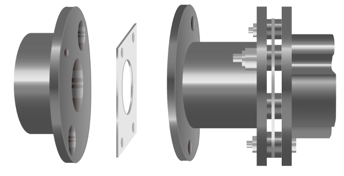
Exploded view
Transmission mechanism that produces high torque
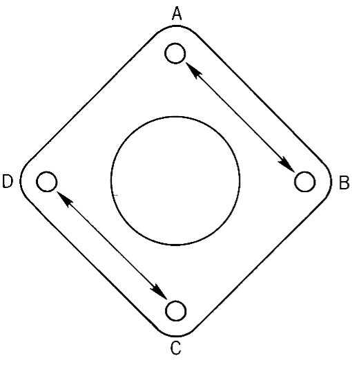
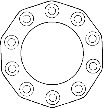
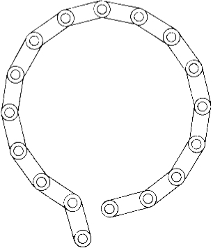
The structural feature of FORM-FLEX® couplings is a flexible element laminated with thin square stainless-steel plates. Holes A and C in the diagram below (center) will be bolted to the hub, B and D to the spacer.
Torque is transmitted as a linear tensile force from A to B and from C to D through the straight section of the flexible element.
Since no complex stresses are generated in this flexible element, the torque transmission capacity of FORM-FLEX® couplings increases.
Drive mechanism that generates less bending stress
By arranging the optimal number of reamer bolts, the bending stress generated in the flexible element becomes extremely small when misalignment or axial misalignment occurs. Of course, the cyclic stress is also reduced.
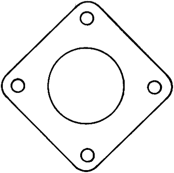
Types of flexible elements
| Performance | Allowable angular misalignment: 1° Allowable torque 33-6,370N・m |
Allowable angular misalignment: 0.5° Allowable torque 3,840-178,000Nm |
Allowable angular misalignment: 0.25° Allowable torque 16,400-313,000Nm |
|---|---|---|---|
| Shape |
【Type A】
|
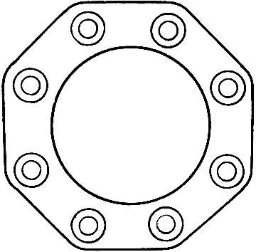
【Type G】
|
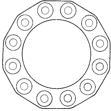
【Type U】
|
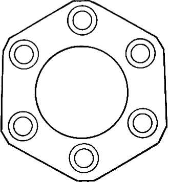
| Performance | Allowable angular misalignment: 0.7° Allowable torque 569-128,000N・m |
Allowable angular misalignment: 0.35° Allowable torque 13,500-256,000N・m |
Number of bolts: 10-20. Contact us as it will be decided each time depending on the usage conditions. Max. torque: 2,000 kNm |
| Shape |
【Type E】
|
【Type S】
|
【Type W】
|
Performance
Allowable axial capacity and allowable parallel eccentricity of the coupling are determined by the type of flexible element and the operating speed. Allowable axial capacity and allowable parallel eccentricity are in inverse proportion; when one increases, the other decreases, so they must be considered concurrently.
Shafts can become misaligned for various reasons. The initial centering will change due to thermal changes, bearing wear, changes in the foundation, etc. In general, the life of the coupling will be longer if the initial centering is done carefully. On the other hand, if the initial centering is not performed carefully, there will be no margin to tolerate misalignment, and the expected operating life will not be achieved.
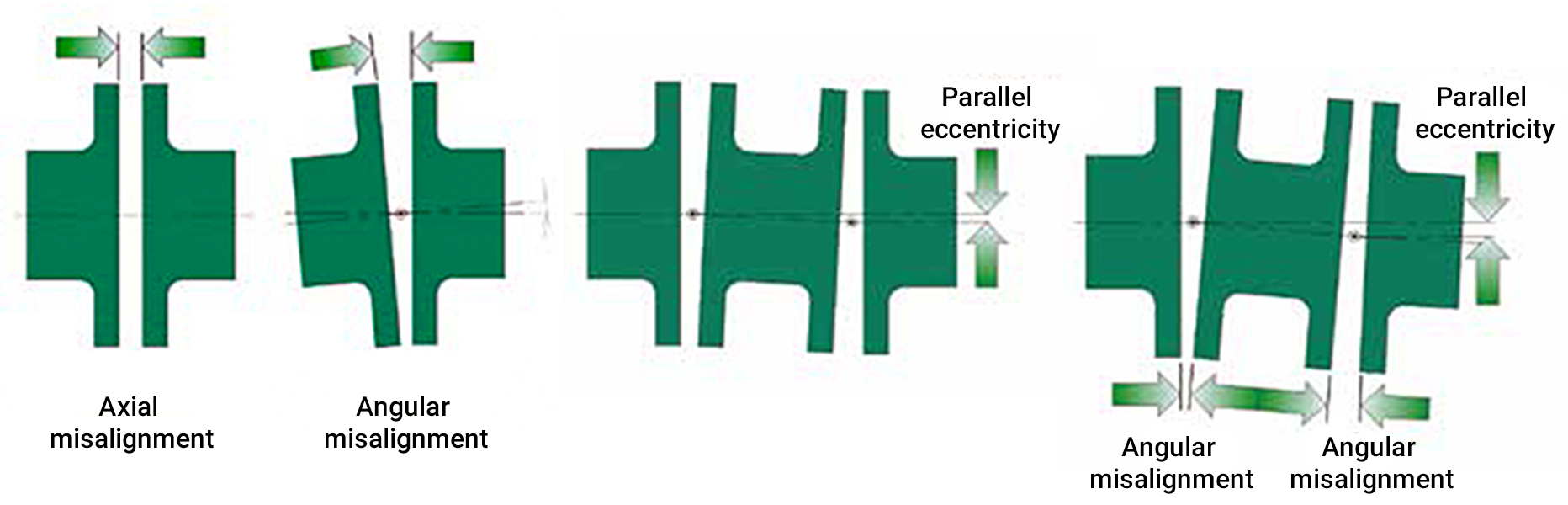
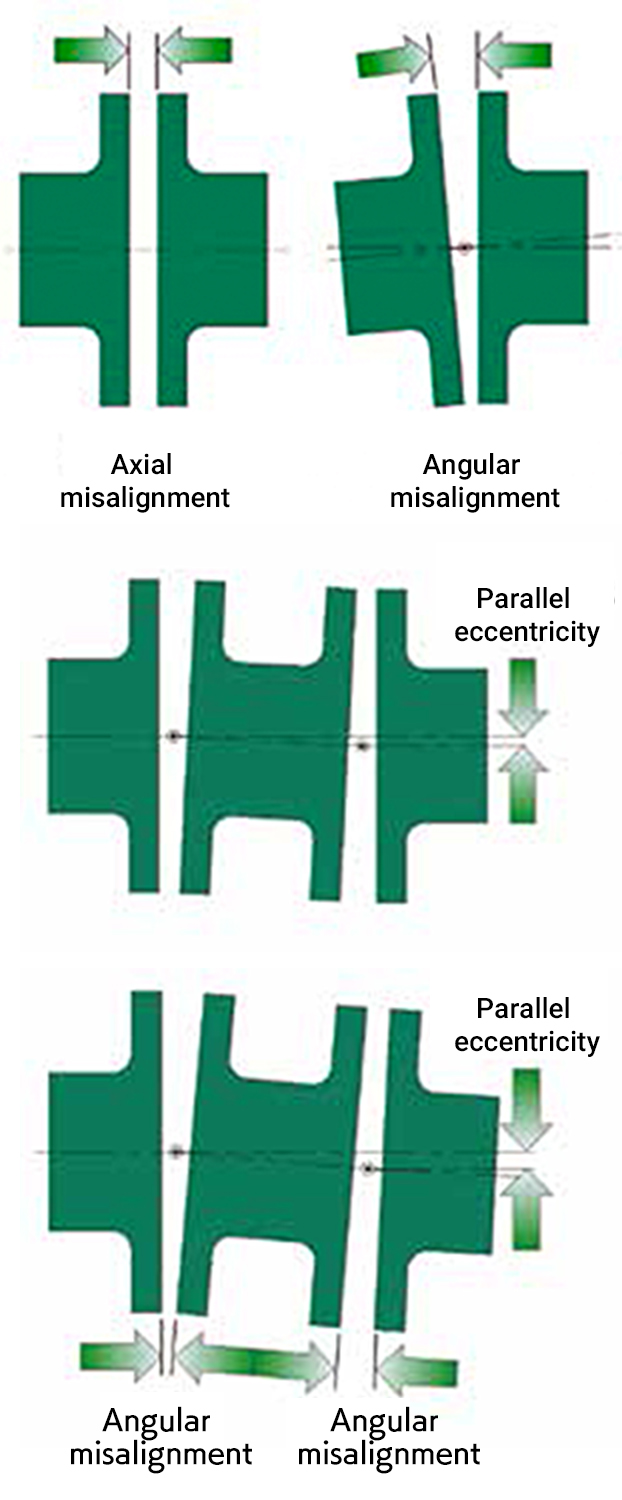
Parallel eccentricity is a condition in which two axes are parallel, but the virtual center lines of each shaft do not match. Angular misalignment occurs when the center lines of two axes intersect.
Axial misalignment is caused by variation in the distance between two axes. Most misalignments occur with a combination of these.
FORM-FLEX coupling satisfies NEMA standard MG1-2003 and JEM standard 1146-1959 regarding the end float of the motor without the use of attached devices that limit the amount of axial capacity. (No additional equipment is required for thrust direction displacement when starting the motor)
Product types and usage
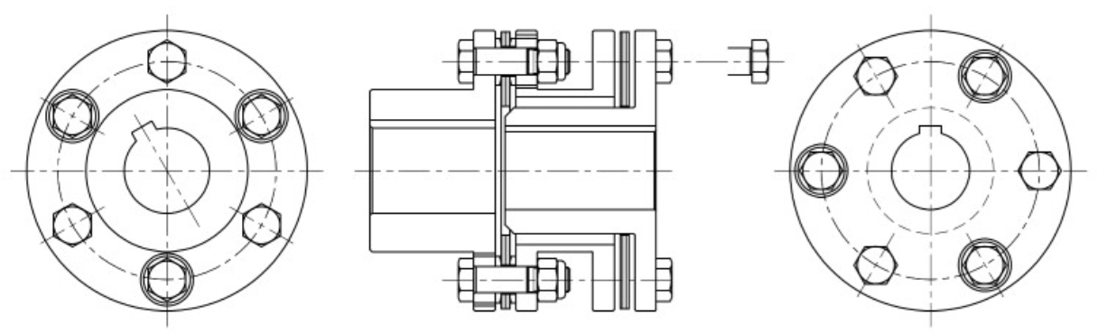
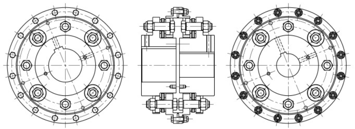
Single flexing coupling
| 4 bolts | 6 bolts | 8 bolts | 10 bolts | 12 bolts | 10-20 bolts |
|---|---|---|---|---|---|
| A3 | E3 | G3 | S3 | U3 | W3 |
Single flexing couplings are used when supported by three bearings. The coupling shown is suitable for large radial loads
As an exception, the method shown in Figure 2 below can be used to connect servo motors and ball screws used in NC machine tools, etc.
In this case, parallel misalignment is controlled by fitting the motor in line with the casing; so the main purpose is to absorb angular misalignment and axial misalignment. However, in this case, overload may be applied to the element, so it is necessary to use an angular element such as FORM-FLEX coupling that is soft and absorbs misalignment.


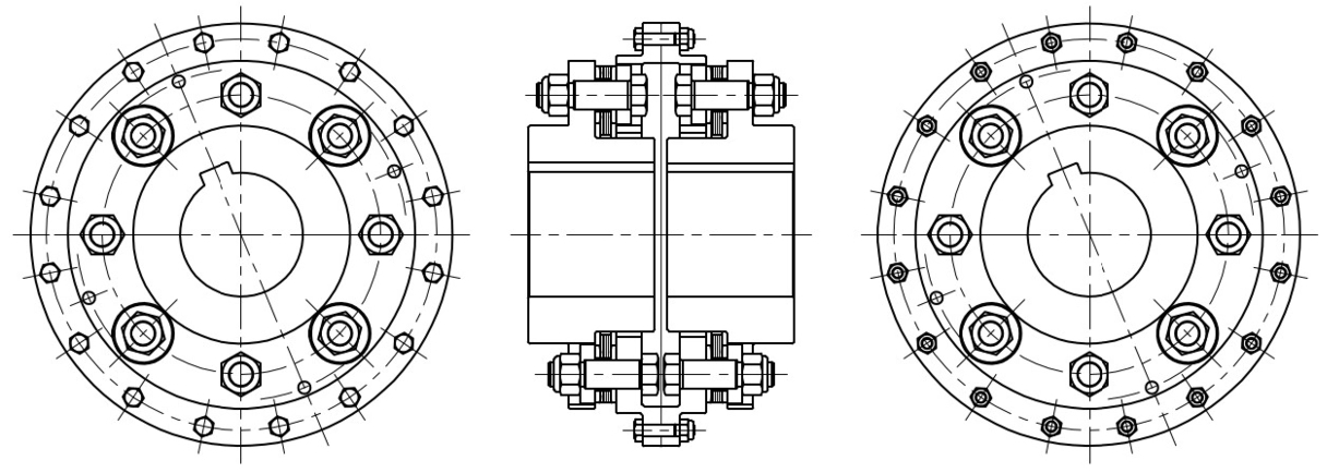
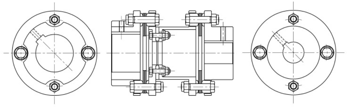
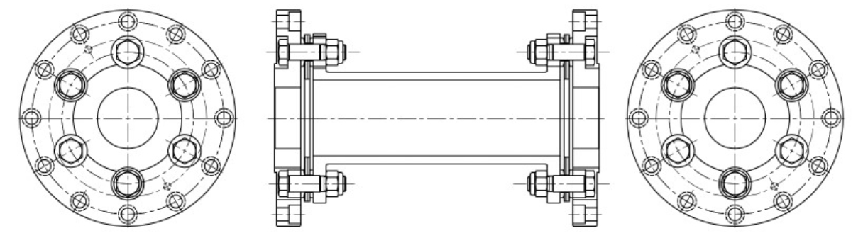
Double flexing coupling
| 4 bolts | 6 bolts | 8 bolts | 10 bolts | 12 bolts | 10-20 bolts |
|---|---|---|---|---|---|
| AX | |||||
| A4 | E4 | G4 | S4 | U4 | W4 |
| AB | EB | GB | SB | UB | WB |
Double flexing couplings must be used whenever the shafts connected by the couplings are both supported by two bearings.
The supported bearings must be within an appropriate distance to the coupling hub.

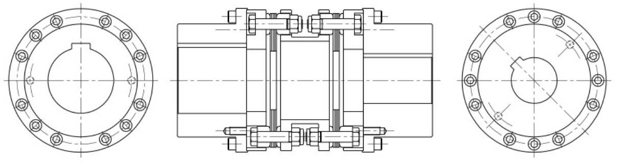
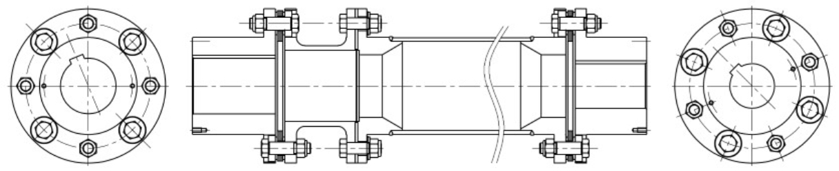
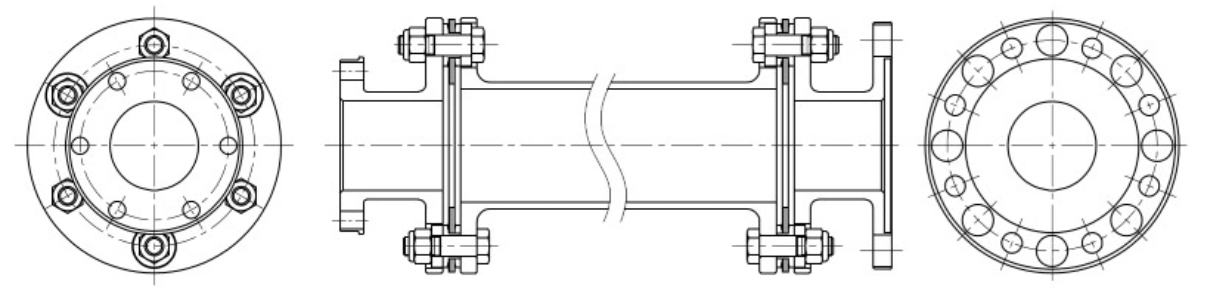
Full floating shaft coupling
| 4 bolts | 6 bolts | 8 bolts | 10 bolts | 12 bolts | 10-20 bolts |
|---|---|---|---|---|---|
| A5 | E5 | G5 | S5 | U5 | W5 |
| A6 | E6 | G6 | S6 | U6 | W6 |
Full floating shaft couplings are used to connect opposing devices that are widely separated.

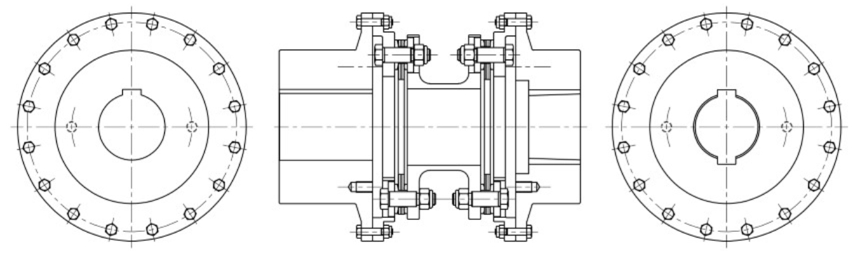
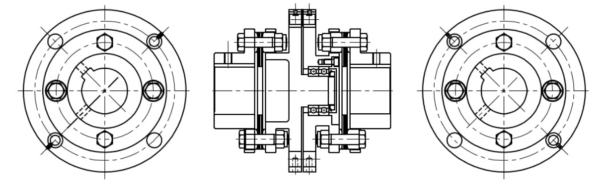
Semi-floating shaft coupling
| 4 bolts | 6 bolts | 8 bolts | 10 bolts | 12 bolts | 10-20 bolts |
|---|---|---|---|---|---|
| A7 | E7 | G7 | S7 | U7 | W7 |
The figure below shows how to use it for reference. In this usage, the shaft is supported by only a single bearing placed as close as possible to the outer sprocket, pulley, etc.
The flexible elements permit radial loads as does A3.

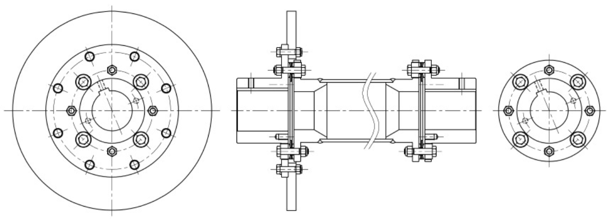
Twin shaft coupling
Twin shaft couplings are combination of semi-floating shaft couplings and full floating shaft couplings, and are suitable for connecting devices with long spans.

Reference diagram of special specifications
Single inverted coupling
Double inverted coupling
Adapter-style coupling
Electrically insulated coupling
Breaker pin coupling
Customized couplings designs
FORM-FLEX® coupling catalog download
Download- TOP
- Coupling business
- FORM-FLEX coupling